The trails,
tribulations, and joys of designing &
making a
telescopic camera
Lucida for the
American Philosophical Society
Jim and Rhoda
Morris
Scitechantiques.com 781 245 2897 Email
Galileo@comcast.net Email
Rhodam@comcast.net
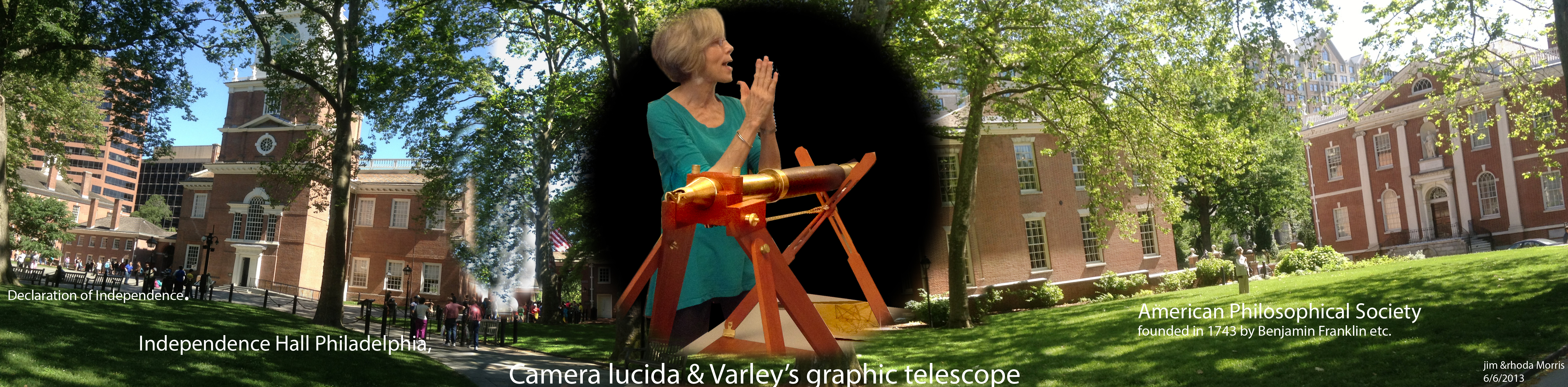
Benjamin Franklin, a self taught civilized man of humor and thoughtfulness, founded this society in 1743 thereby connecting the Arts and Sciences in such a way that the expense of the learning experiences gained could be shared by its members and at least by some of the community. An achievement even before our American political revolution. The perseverance of science and the tradition of Ben's sprit continues today. We are pleased to have participated in one of these connecting programs. This note tells our part of the behind the scenes stories of building an English Varley PatentedGraphic Telescope Machine using parts from an English made telescope, redesigned with American adaptability, assembled near the American revolutionary town of Boston for the World to see.
The picture above shows the location of the American
Philosophical Society Museum amidst the buildings of the historical Independence
Hall complex in Philadelphia. A wonderful collection of symbols for how to run a
community, a country, studying the laws of Nature and nurturing the laws
of Civilization.
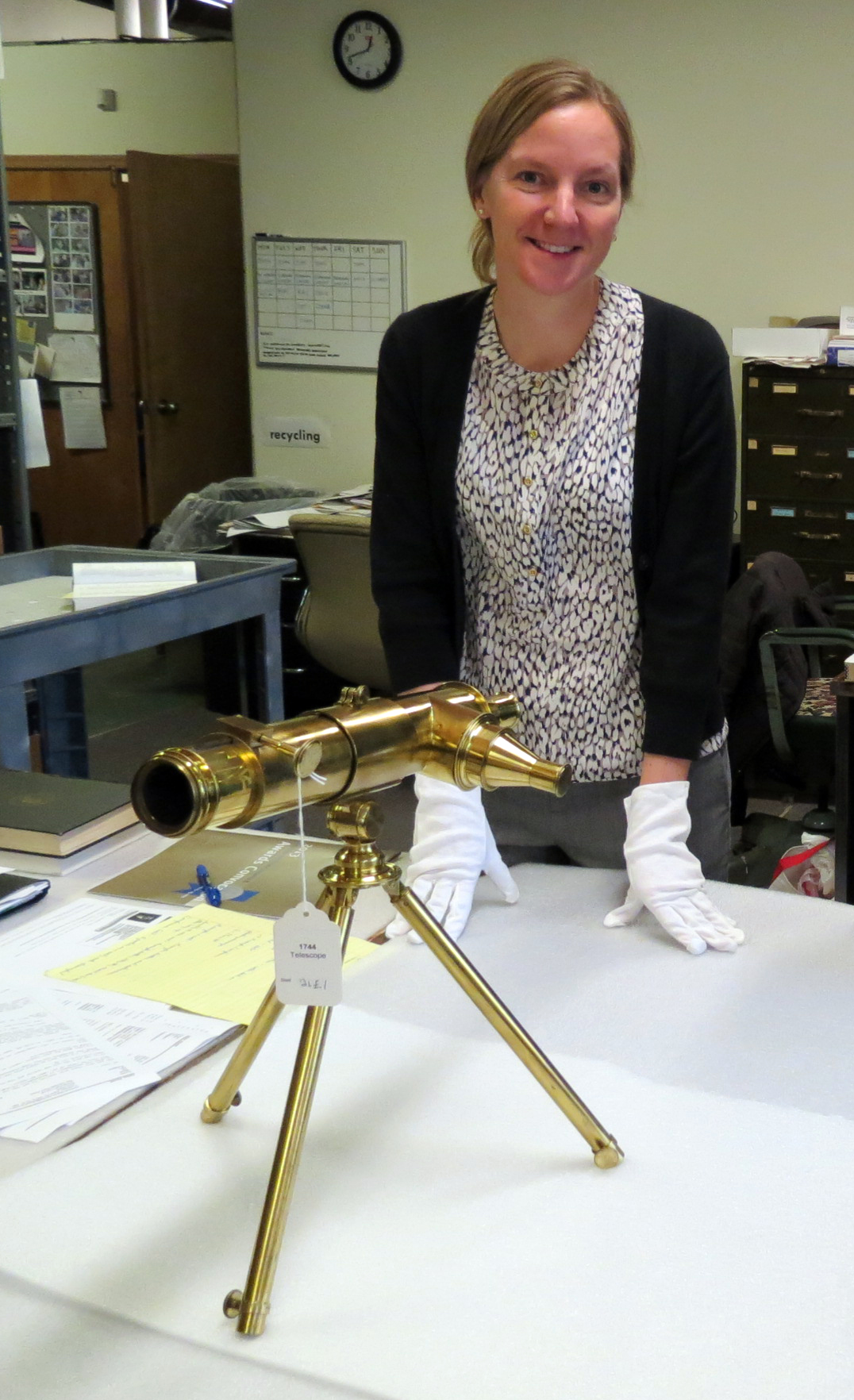
In the center is the director and curator of the museum, Sue Ann Prince,
admiring the Varley graphic telescope we built for them and anticipating
the joy their visitors will have in using and learning from it.
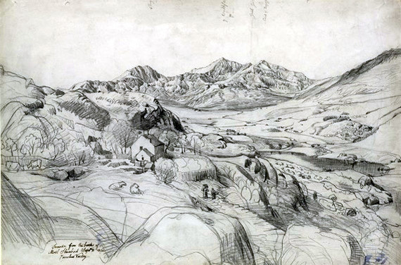
Cornelius Varley was an artist,
astronomer and scientific instrument designer and builder, bless him.
He developed and built Lucida type graphic
telescopes to allow scientists and artists to produce more precise
drawings and paintings of distant natural and artistic subjects reaching to
mountains and stellar objects.
He also adapted his instruments to microscopes giving a view into the
wondrous and complex world of tiny objects, satisfying our
scientific curiosity and aiding us in artistic studies.
His instruments render a wider and deeper scope of nature's world for all of us to see and wonder at.
He achieved this feat at a time before cameras were available.
He left, actually willed, this still remarkable drawing aid for those who want to
reveal the artistic view of
nature.
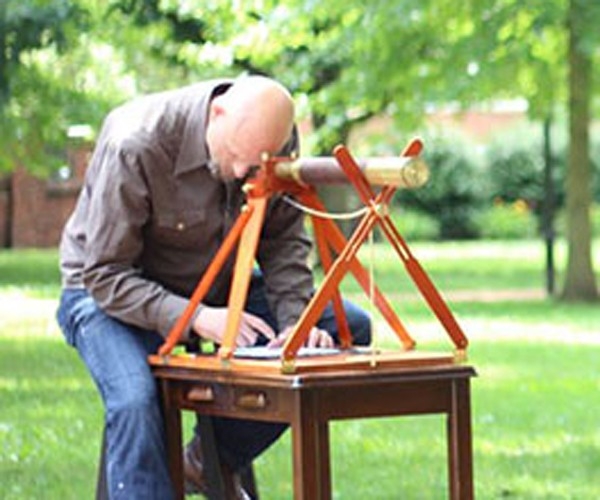
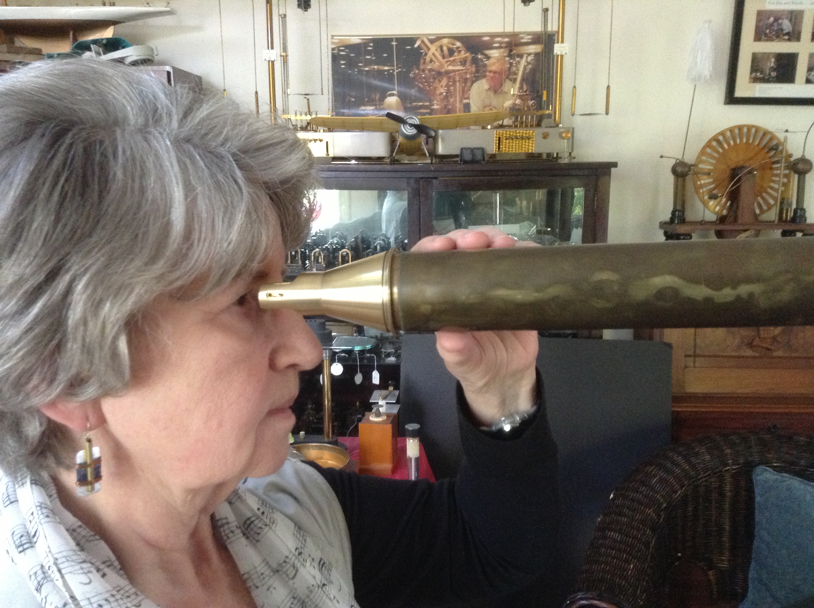
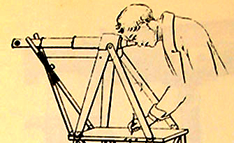
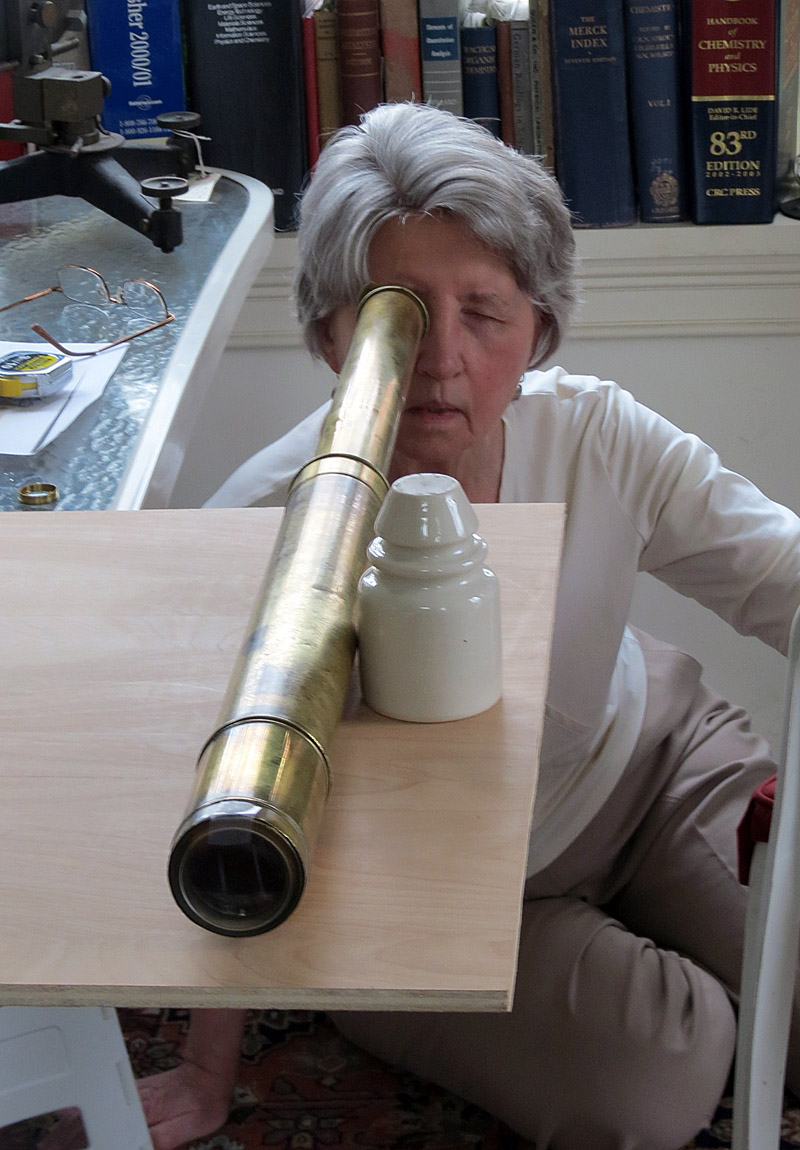
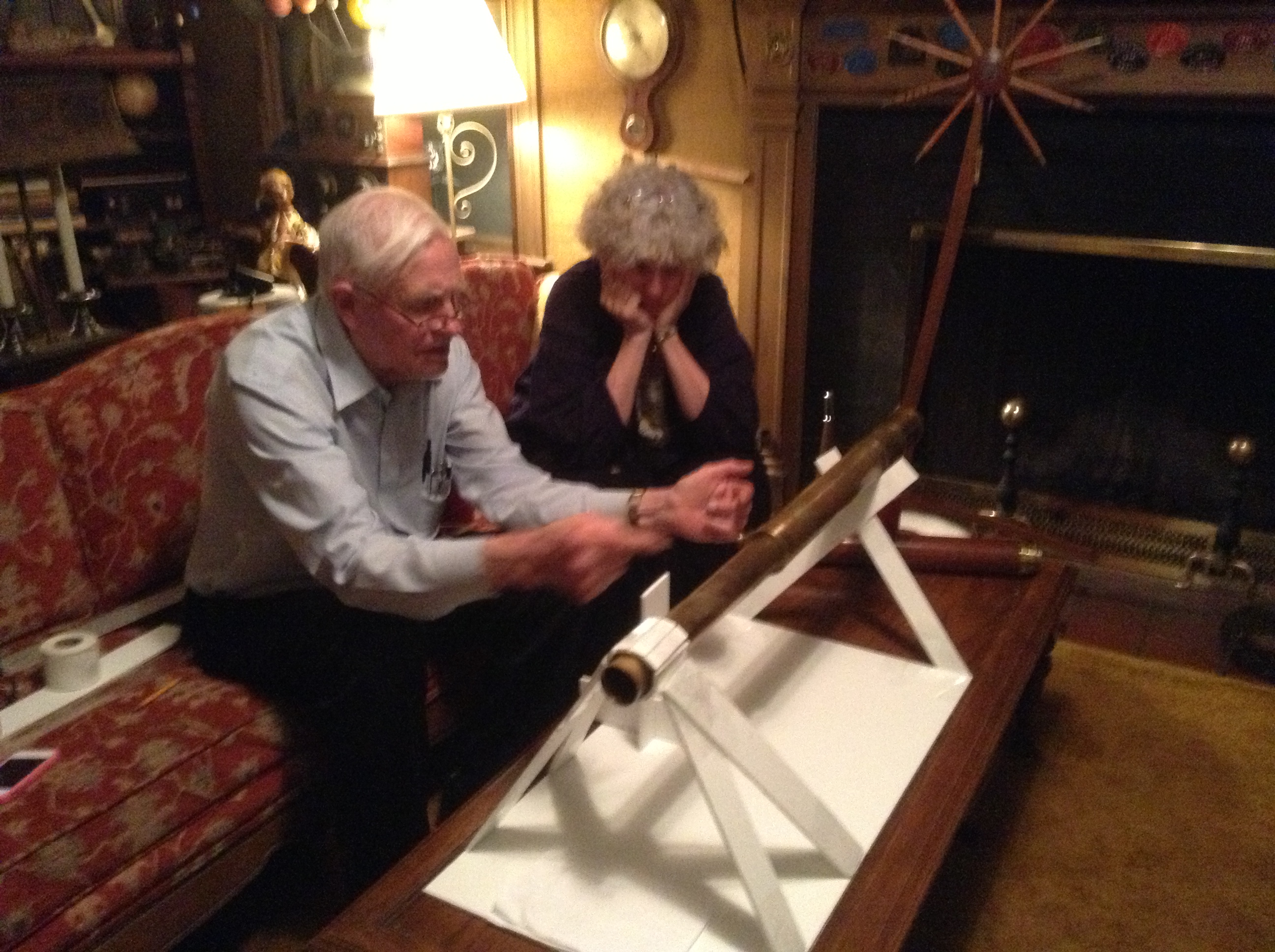
And not of least importance, his instruments can be used for just plain fun for seniors and
juniors alike, as shown below.
 |
 |
 |
 |
Each of us plays an important role in society and our views can be expanded and shared by using this type of instrument. Here is one small chance to see nature in action and pass along what we see and learn. One can search out and study each detail as we trace the object we we see in the telescope at the same time recording it with our fingers holding a marker on the table below. We then have the joy of learning about the object in greater detail and sharing our experiences with others.
Purpose of this Web Site:
This web page has been put together by Jim and
Rhoda Morris. Our intention is not to organize it as an instruction book
on "How to make a Varley Lucida type graphic telescope in 20 easy lessons or
less" although one might, in practice, be able to use it for that purpose.
So what are these pages about?
We hope by furnishing our records, our experiences and our
pleasures in building this working example of Varley's instrument for the
public's use, that we will also be carrying on, in one small part, the tradition
of Varley's work and his wonderful instruments. The opportunity of being a part
of such a story can be envisioned by roaming through of our notes, pictures,
discussions, descriptions, and videos of the issues we dealt, the instruments
involved and especially the people we worked with as we built the Varley
telescope. Our presentation is an informal tour that also shows how the
Varley telescope is a further and much broader development of the camera lucida
invented only s few years earlier.
 |
Kristen Frederick-Frost was our principal and very helpful working contact at the American Philosophical Society. Here she is standing in front of one of Varley's telescopes at the Franklin Institute. We were making detailed measurements and took photographs of the essential parts of the eyepiece we needed to replicate. |
Kristen and Rhoda in another setting another time and project. We are at England Rhoda and Jim were in the process of getting data for another film the Mystery of Matter where we were replicating an apparatus used by Henry Gwyn Jeffreys Moseley in his classifying of elements for the periodic table and experimental evidence in favor of Niels Bohr's theory. We met Kristen here while she was at Oxford University. |
 |
Our goal was to help continue the odyssey of a famous era in both science and art by repeating and adding to this saga of science and its adventure. It is more than just a log of our consultation with the museum staff about our progress and decision making process. This material, hopefully, can be appreciated as being a part of a continuing journey through the history of the arts and sciences to today. One that can be realized by those who are fond of both. Some may also appreciate getting an insider's view of what it is like to be an active part, a member, of this process.
In the beginning our question was:
What was Varley's main
contribution to the science of the art he was endeavoring to produce? The answer is:
The basis, the very heart, of Varley's
instrument is a 'mirror knife edge' that allows the observer's eye, when placed
as close as possible to the eyepiece, to simultaneously see the object and the
drawing stage where he or she can copy it.
%20EYEPC.jpg) |
 |
| THE EYE PORTION OF THE EYEPIECE SHOWN ABOVE IN THE TELESCOPE IS THE ESSENTIAL PIECE. THE KNIFE EDGE MIRROR IS THE KEY ALLOWING THE OBSERVER TO SEE BOTH THE OBJECT AND THE DRAWING AREA AT THE SAME TIME. | RHODA LOOKING THROUGH THE EYEPIECE CHECKING THE EYE RELIEF ON THE TELESCOPE TO MAKE SURE ONE GETS THE MAXIMUM VIEW OF THE OBJECT WITHOUT GETTING TOO CLOSE AND INJURING THE EYE. |
We were delighted but over booked when asked to build a Varley telescopic camera Lucida. We already had considerable experience with these sort of projects. They are always delightfully accompanied with trials and tribulations when replicating very historically famous instruments. This instrument was needed for the American Philosophical Society Museum's (APS) summer / fall 2013 season exhibition. There were many conditions to be met. First of course, it had to fit the museum's delivery time, its budget, and its safety demands. The instrument has a very sharp edge on the image divider which is very close to the eye when the user is copying the image. The construction of the instrument had to meet as close as possible all the fabrication styles and components for that period. Most importantly it had to operate just as if it were an original Varley instrument. It also had to survive the untrained handling of the instrument and its delicate parts by younger visitors.
And there were more. There was the issue of redesigning, developing, adapting the optics in this telescopic version of the camera Lucida to take into account the museum's space constraints when used inside and still have it be useful for distant objects if and when it was taken outside. NOTE that in general telescopes are designed to bring distant objects close up, not close up objects closer up. Also the eye relief had to be extra long to provide room for the critical distance between the eye and the first lens. Our independent research was absolutely essential
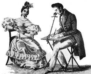
Analogy to the Camera Lucida
As for the issue of the basic component that makes the Varley instrument work, the knife edge, it has a similar function as the prism in the camera lucida for simultaneously seeing the object of interest superimposed on the drawing. Start with the very confusing photo above. Refer back to it while looking at the much copied art work below for how a camera Lucida works. Careful, careful! NOTE, look for the classic faults in this historic drawing of scientific instruments. Artists have to only use creative license to do their best work, by contrast scientists get fired if their device doesn't work.
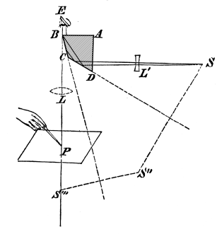
The drawing of the optical ray paths has misleading errors
in it. Can you spot them?
Jim & Rhoda Morris 781
245 2897 Galileo@comcast.net
K1ugm@comcast.net
Rhodam@comcast.net
http://www.scitechantiques.com
Camera LucidaFrom Wikipedia, the free encyclopedia
|
Below: are nine photos of our Camera Lucida from our collection which we had the pleasure of loaning to the American Philosophical Society Museum followed by series of photos of our process of replicating Varley's telescopic graphic camera lucida for their exhibition.
.jpg)
1. Prism and peep sight
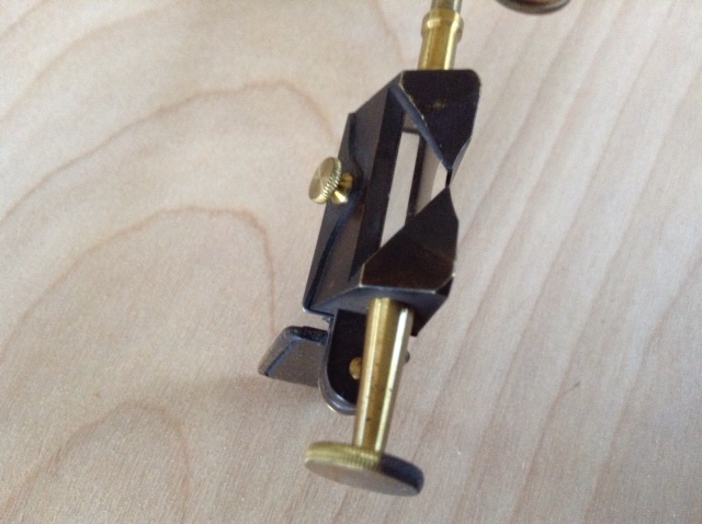
2. Side View of prism
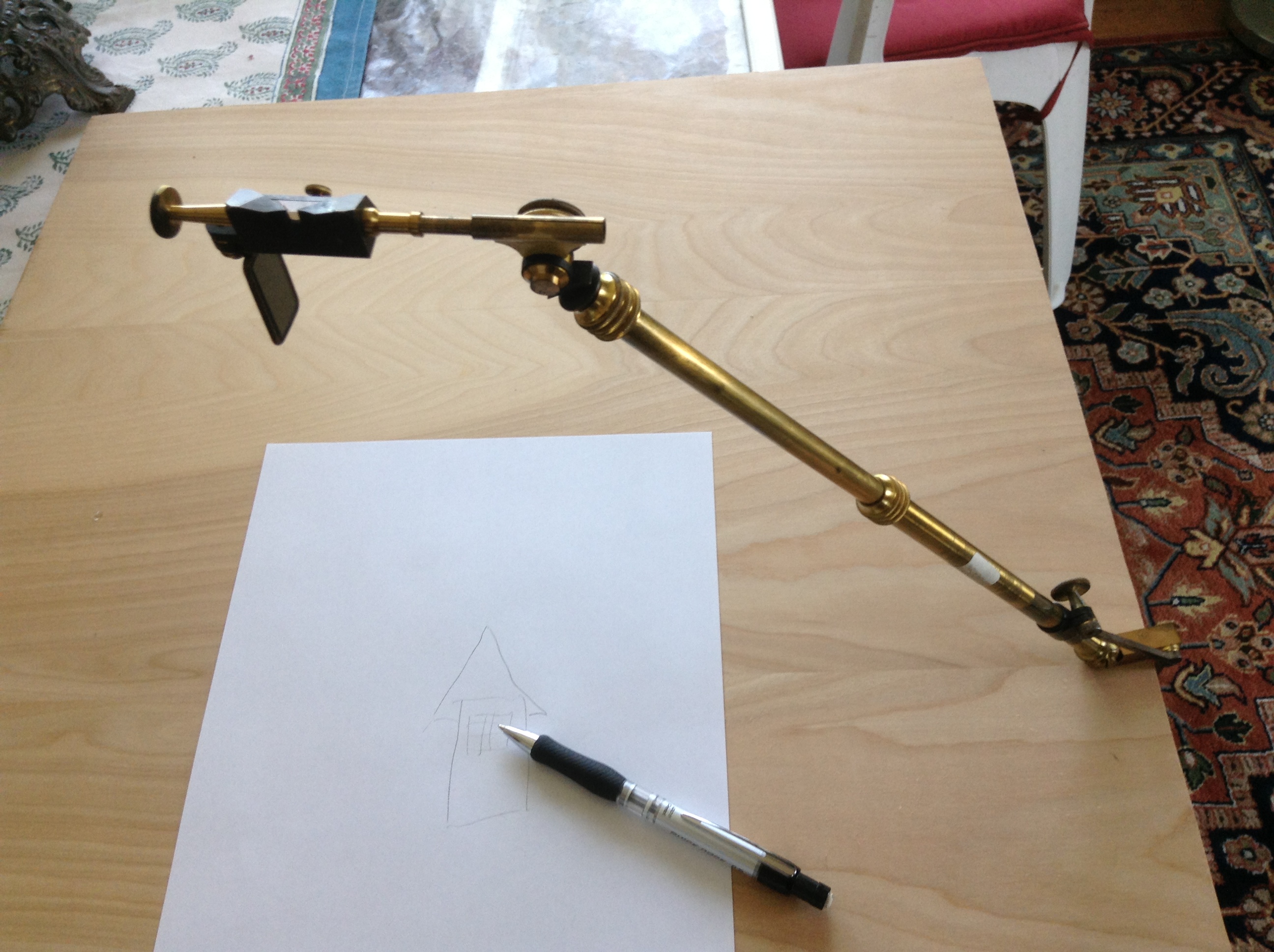
3. Camera Lucida set up on drawing board

4. Top view

5. Clamp for fixing the Lucida to drawing board

6. Another view
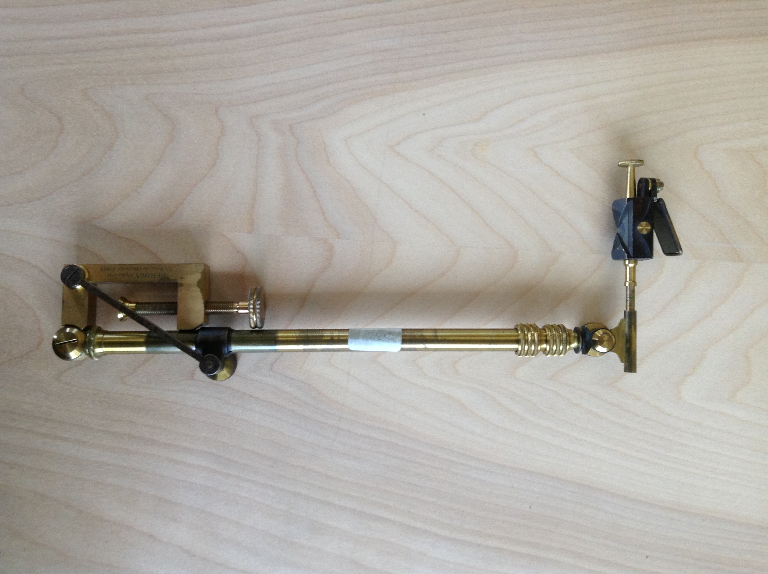
7. Folded up ready for packing the unit into its carrying case
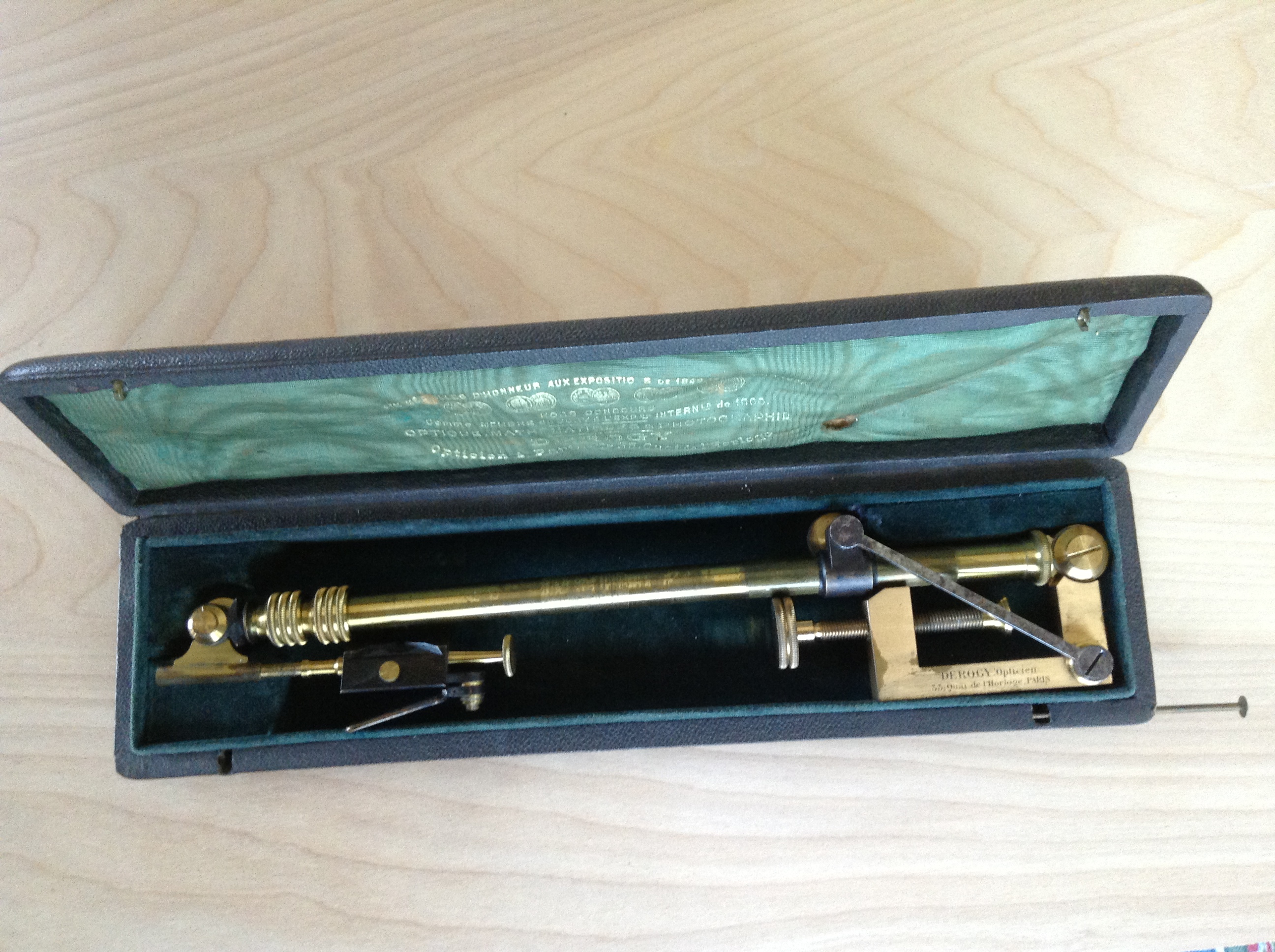
8. In the carrying case

9. Inscription on clamp
Building the Varley Patented Graphic Telescope
|
In addition to providing our camera lucida
described above, We follow this with a series of very interesting photos and notes taken during the rebuilding of the period Spenser Browning telescope to a Varley telescope by replacing the Browning eyepiece with the complex Varley eyepiece and modifying the objective end for perpendicular and closer viewing of objects. |
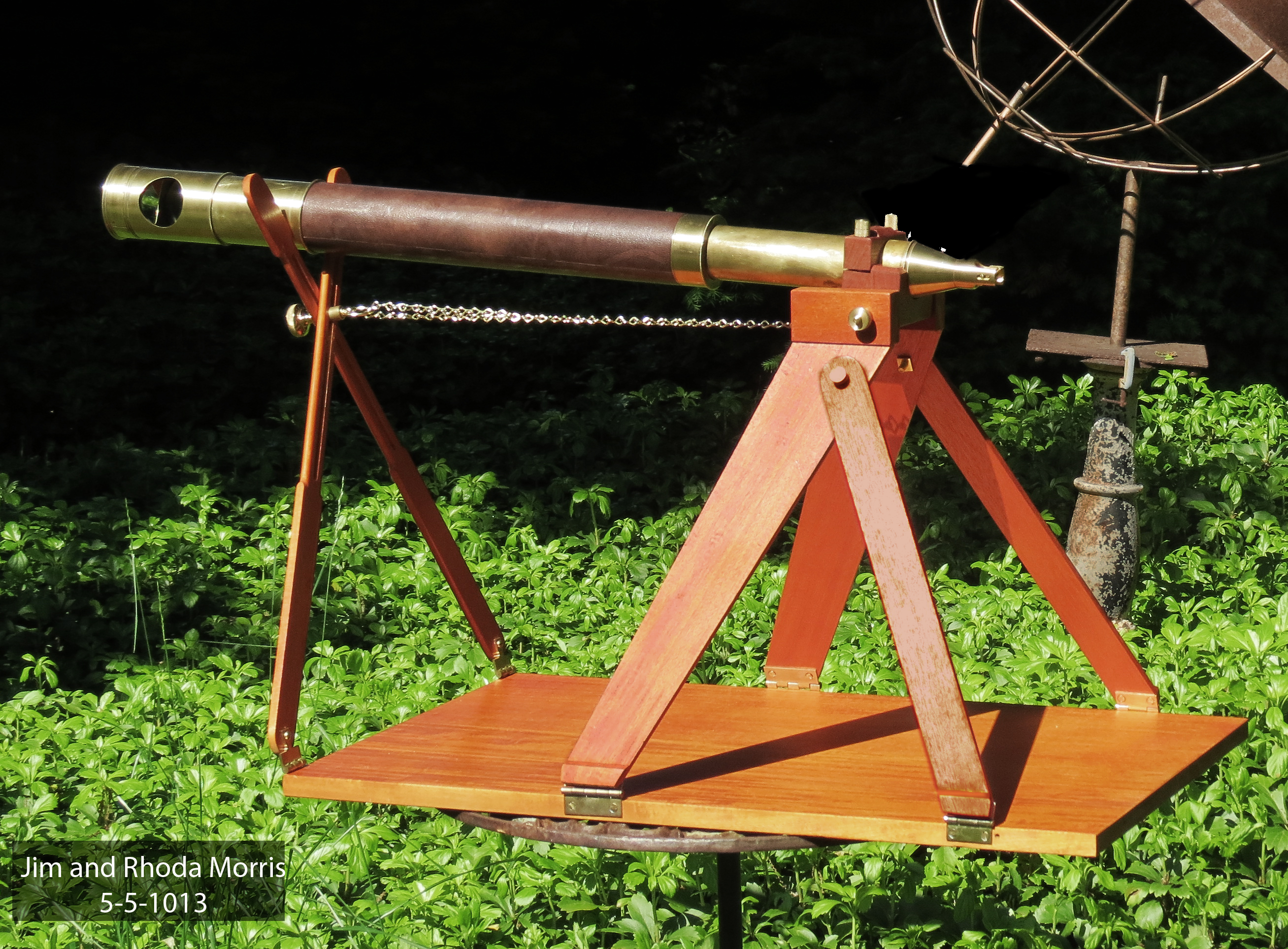
The start and the finish of the instrument.
 |
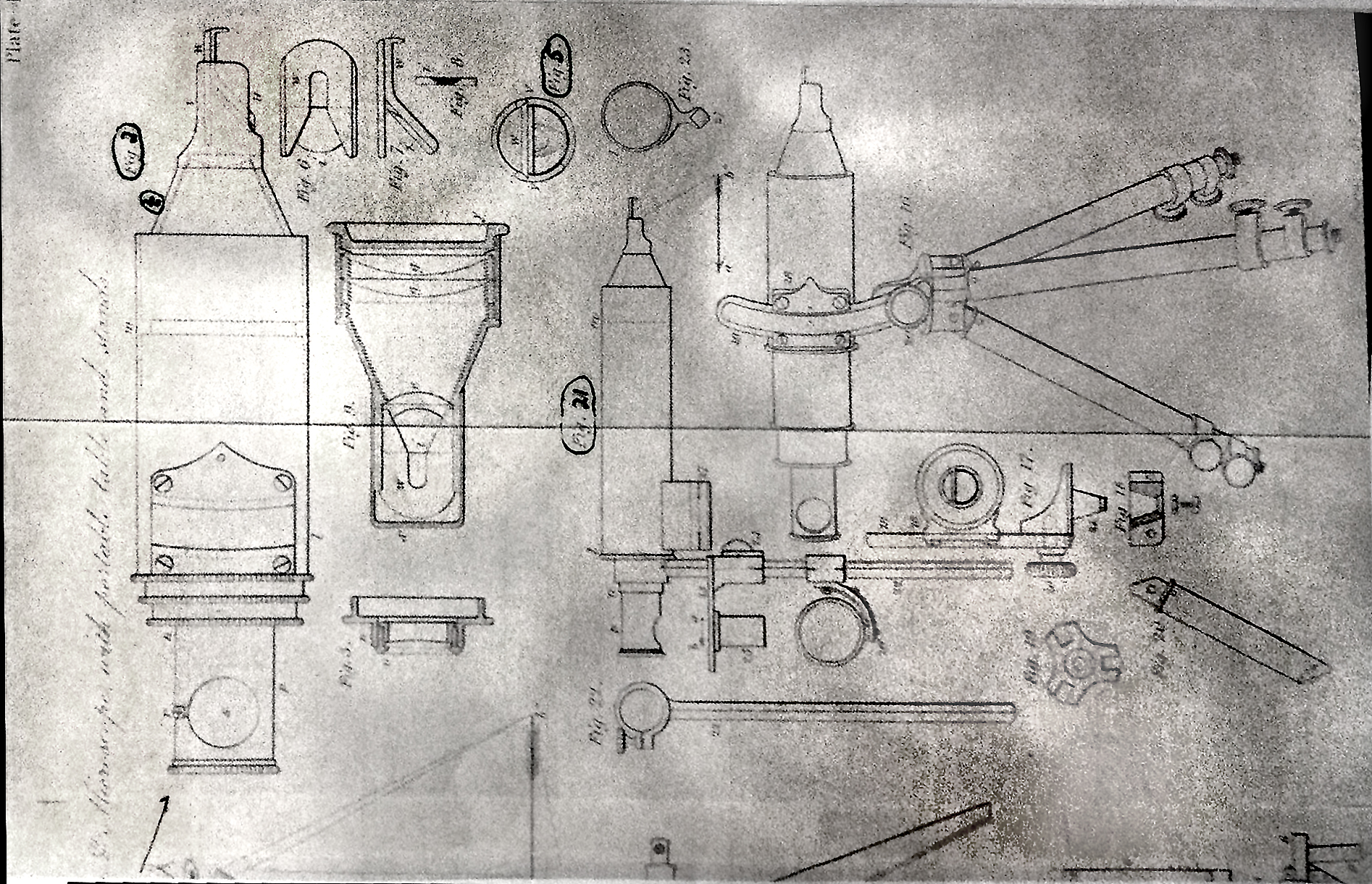 |
| Varley's drawing of one of his suggested wooden folding apparatus for holding the telescope holder. As one can see from the photo below we chose the one in this drawing to replicate. | A page out of Varley's patent showing the details of the eyepiece lens including the knife edge mirror, and its mounting. Instruments rarely follow the patent drawings. Varley was all over the place. His drawing and sketch were over a large range of topics and brilliant. |
To meet the budget requirements without straying too far off from the details of the telescope we chose a super fine Spencer Browning telescope of the same period. It needed some cosmetic repair, but had an extraordinary optical system and performance ideally suited to the Varley needs. Our license in this matter was that Varley made a fairly large number of telescopes and the ones that still exist have physical appearances and construction all over the map in size and construction. The principal difference between our telescope and existing Varley scopes is that the one we substituted does not have a smaller diameter at the objective end than the body. Another possible justification in the agreed substitution was that Varley could, and probably did, use a standard telescope for his starting experiment with his knife-edge mirror. Wouldn't it be satisfying if he used the same telescope we have chosen?
Below are photos of the original Spencer Browning telescope we used and its conversion to a Varley type Graphic Telescope:
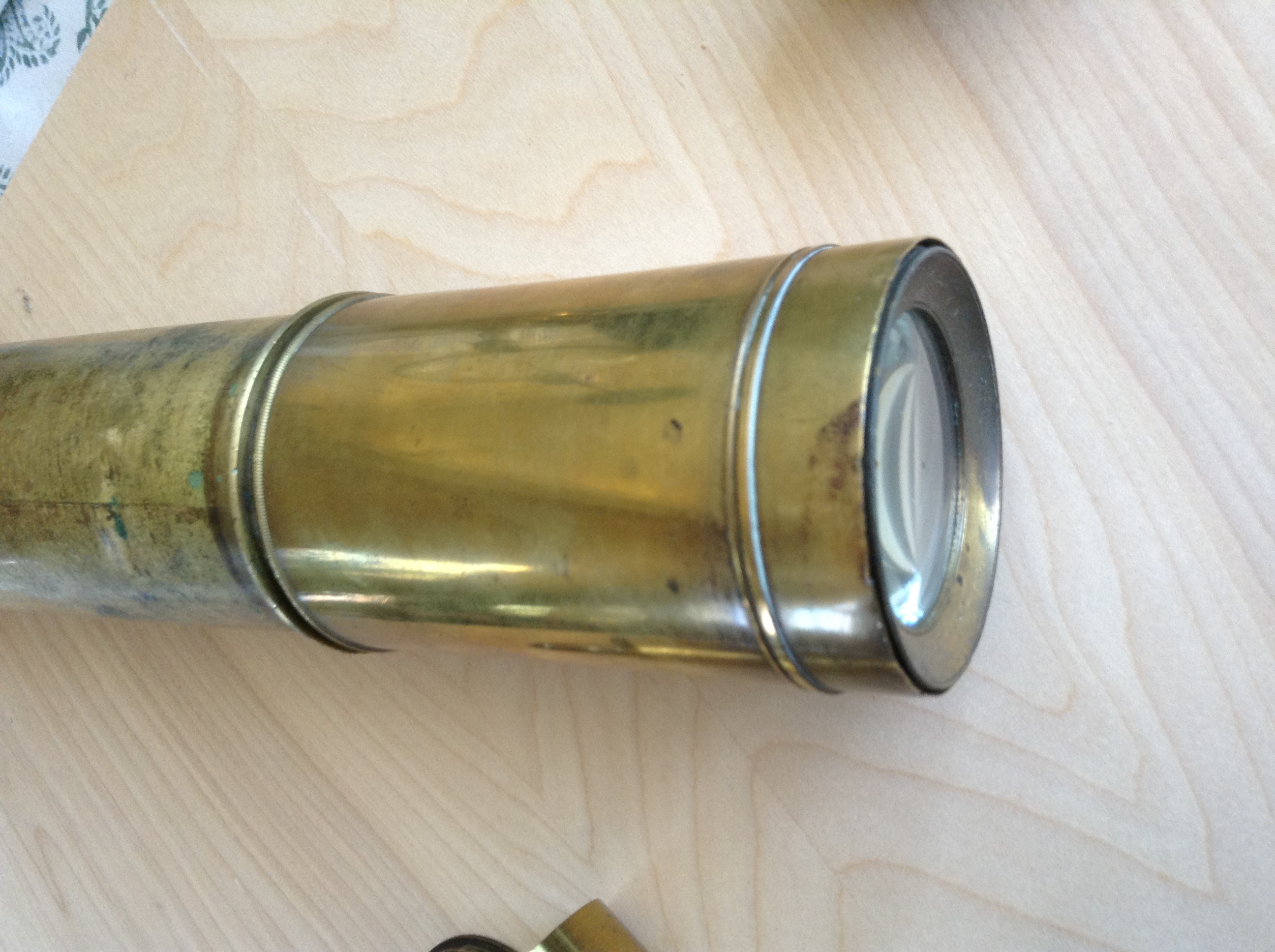
1. Below, The telescope lens section of the Browning partially extended and the beginning of the disassembling of the eyepiece.
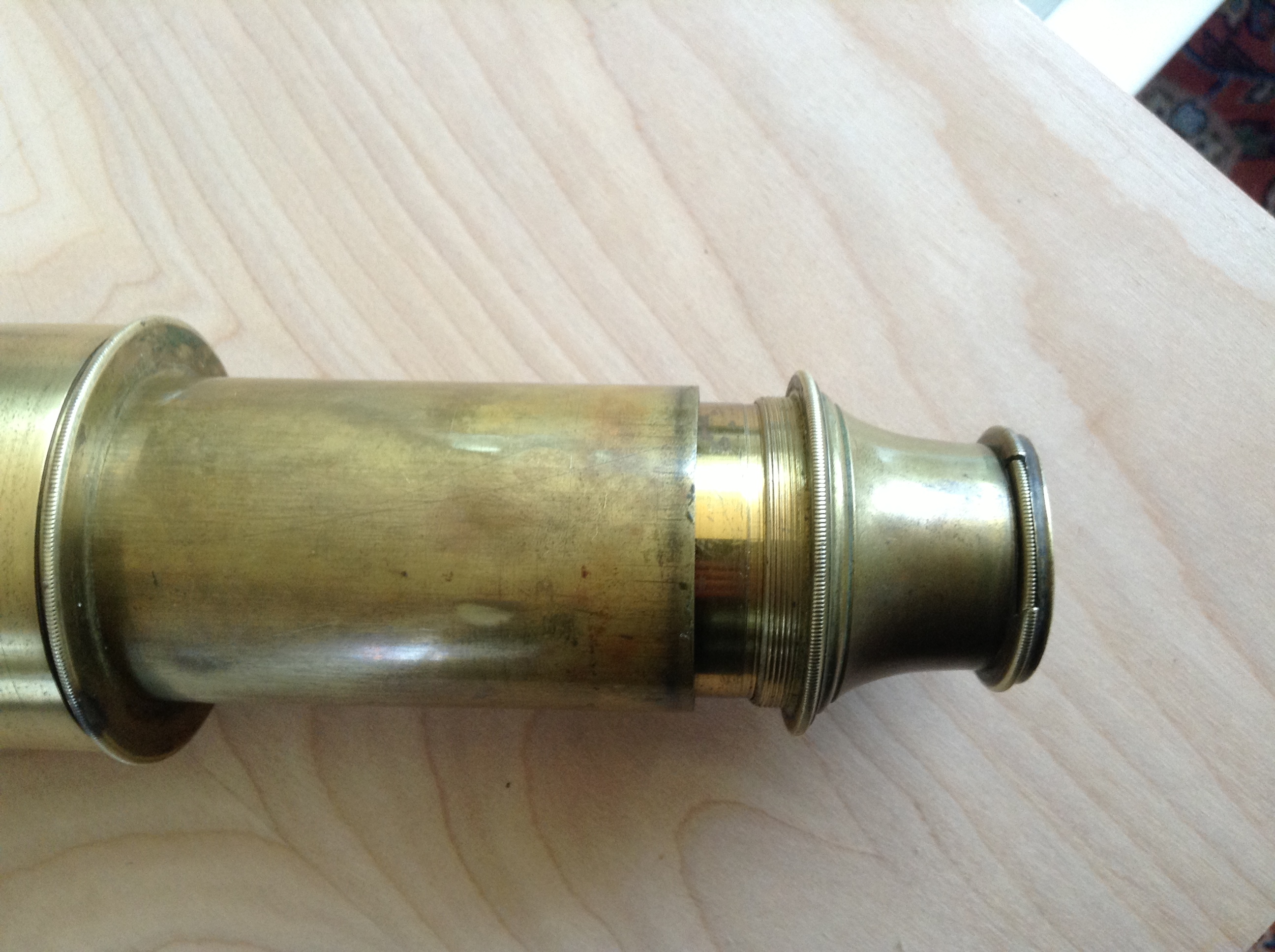
2. Exiting Spenser Browning eye piece partially unscrewed and drawn from telescope.

3. The two lenses in the eyepiece to be used in the conversion to a graphic telescope

4. Same as 3 with eye multi-lens eye eyepiece piece lens removed from its holder
5.
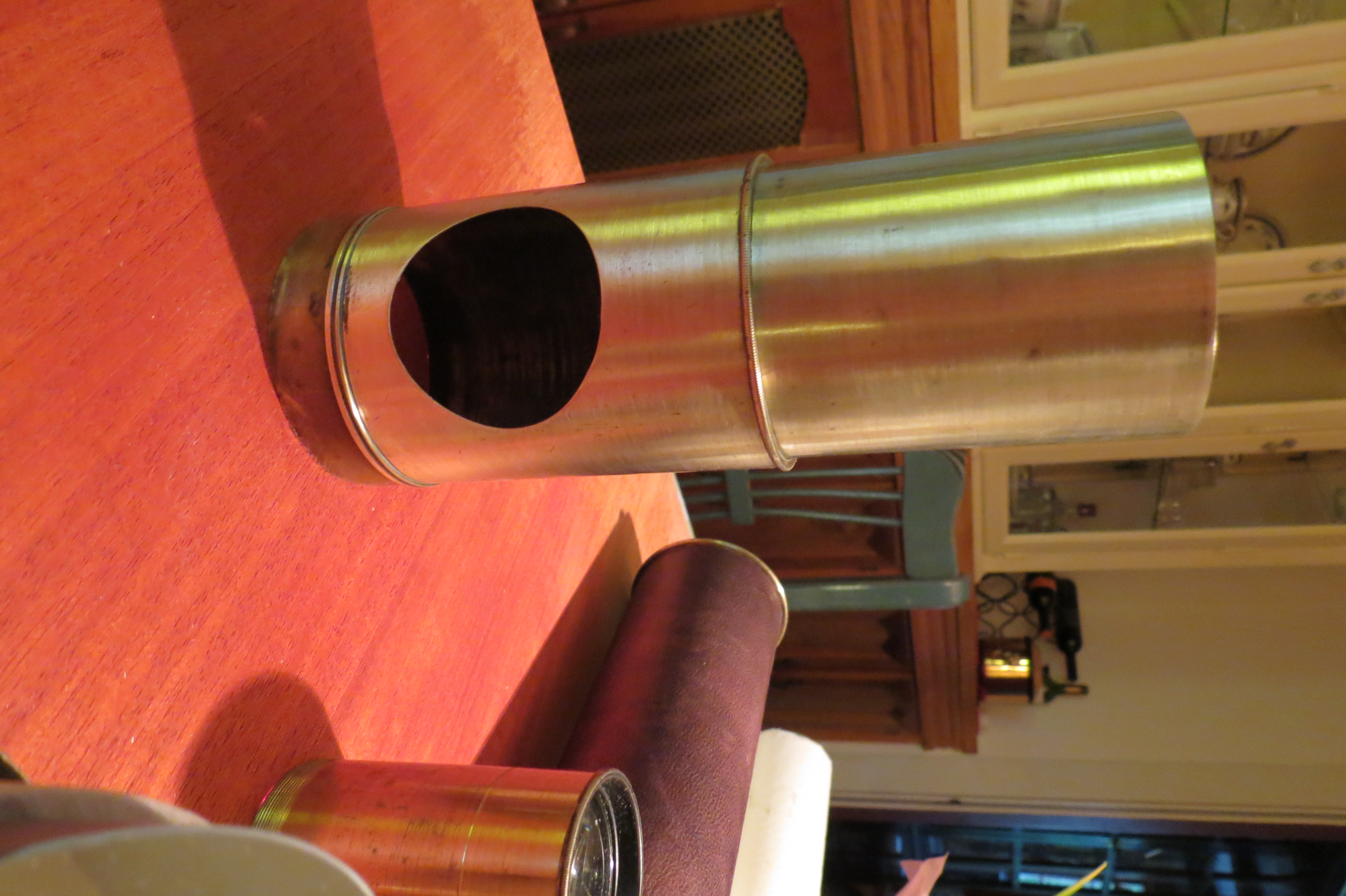
Objective end with hood pushed back to expose the lens. We will have to
construct the
rotating mechanism for holding the forty five degree
precision optically flat surface mirror.
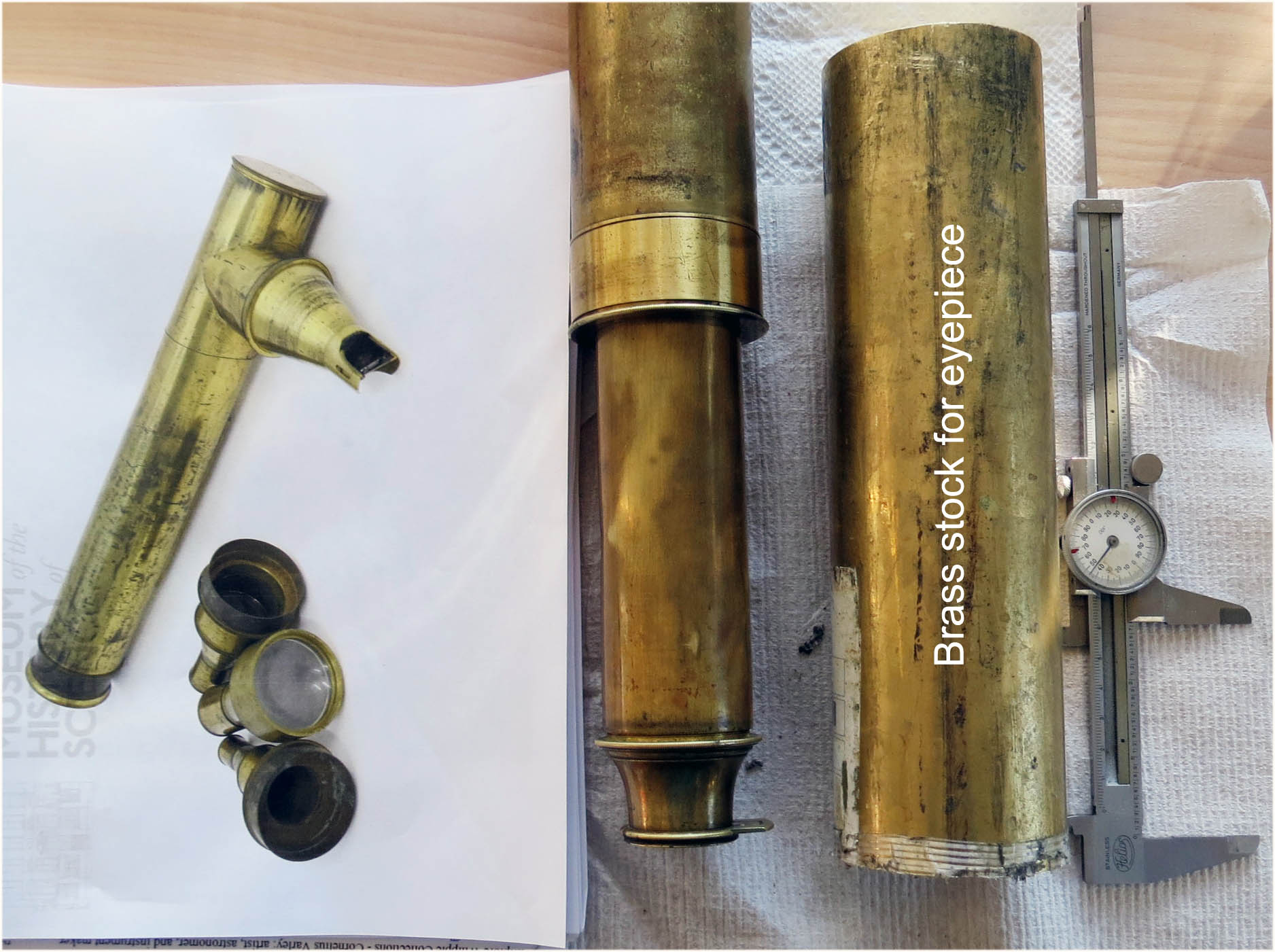
6. On the right is a photo of a collection
of Varley lenses and an example of one of many body types
he used to hold
them. In the middle a piece of brass stock, 2 3/4 inch dia 12 inch long,
of which a 4
inch long chunk will be used for make the eyepiece. Further on one will see the
reason for this chunk of brass.
| Below are Notes and Measurements: furnished to the American Philosophical Society
Museum
during our work. a. We made arrangements to restore the
leather covering on body of the period Spencer Browning & Co. London Day and
Night telescope. d. At a distance of 10 feet from the objective, the
maximum field of view is 4.5 inches ????? |
.jpg)
7. Photo of Franklin's PGT 011 from Kristen's
email 3/25/2013.
AGAIN THE CRITICAL PART IS JUST THE LEFT ONE INCH
STUB OF THIS EYEPIECE.
Below it is superimposed on a photo of the Spencer Browning
telescope eyepiece, from photo # 2 .
WE HAD TO EXTEND THE DISTANCE BETWEEN THE LENSES A BIT TO
INCREASE THE EYE RELIEF OF THE TELESCOPE.
 .
.
8. Comparison the physical fit between the two
eyepieces by superimposing the photo of the
Franklin PGT 011 (white outline) over the Spencer Browning
eyepiece (see our photo #2)

9. Top photo displays a number of Varley eyepieces and one of
the many telescope bodies he designed.
We show this because Varley made many
different models justifying our use of an equivalent telescope
which at little to no loss of integrity enabled us to decrease the construction time
as well as be more cost effective.
The bottom photo shows the roughed out conical portion of our model of Varley's
eyepiece on its way to the final stage.

10. Top photo shows another view on left of our
roughed out cone for the replica . On right
are parts of the
original telescope we are adapting. Our changes will be reversible.
(The cup of tea at the top of the photo had been set out in case Varley's
spirit stopped by for
a visit. Note the cup sort of hovering above without
any visible support. Is that a bit of star dust sprinkled
about the photo?
hmmm (-:
11. Close up Rhoda measuring the field of view and the
shortest distance from objective to the telescope
with and without the extender objective lens. This was very important to
shorten the distance
between the telescope and the object to allow the
telescope to be used inside the museum which
was a little shy of available distance.
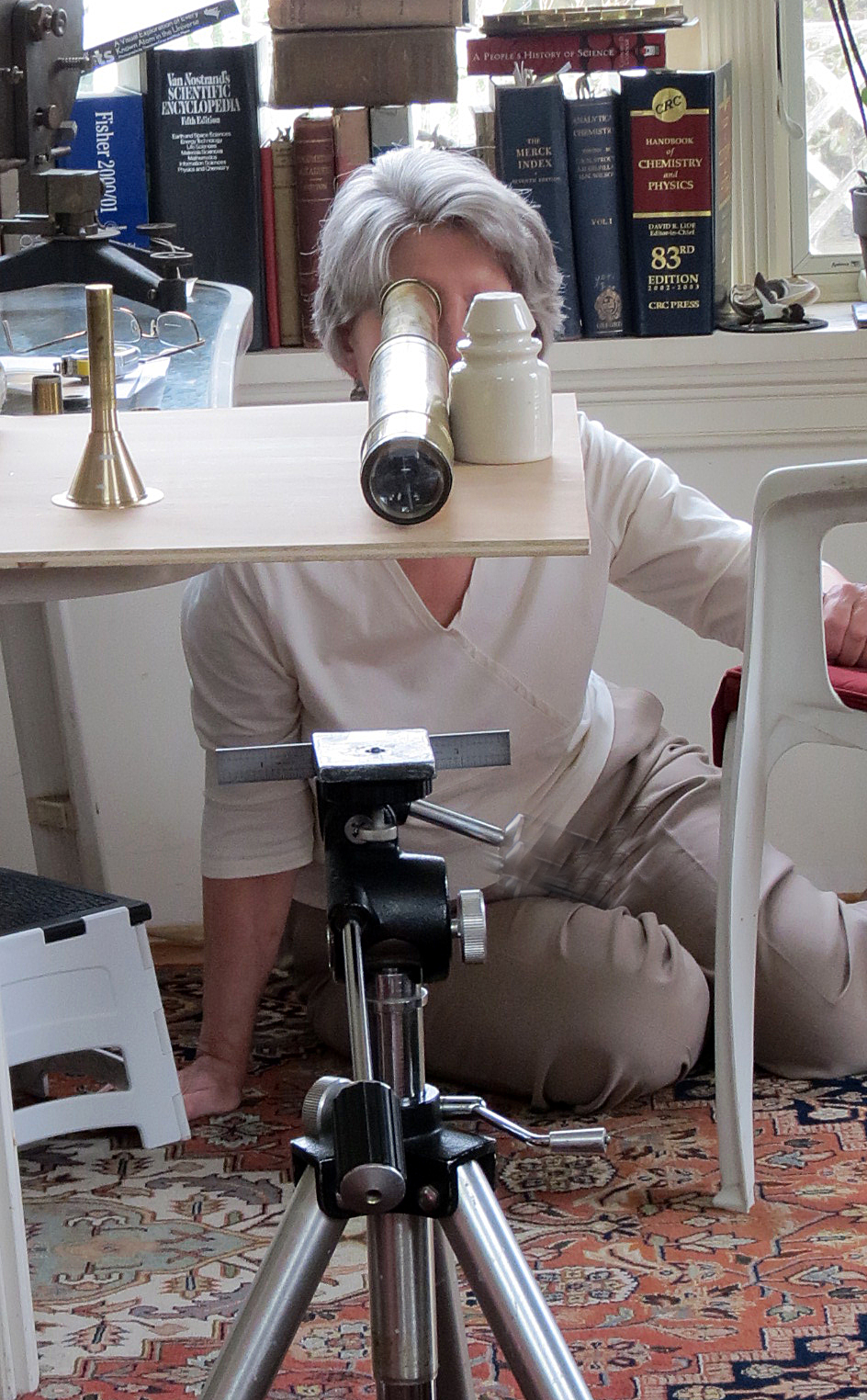
12. The tripod holding the scale for measuring the field
of view and the shortest distance from objective
to the object
with and without the extender objective lens. To the left on the
table is the roughed out eye
piece for holding the eyepiece optics of the
replica .
Below are Detailed Pictures Showing the Fabrication of the Varley Telescope Eyepiece Fixture
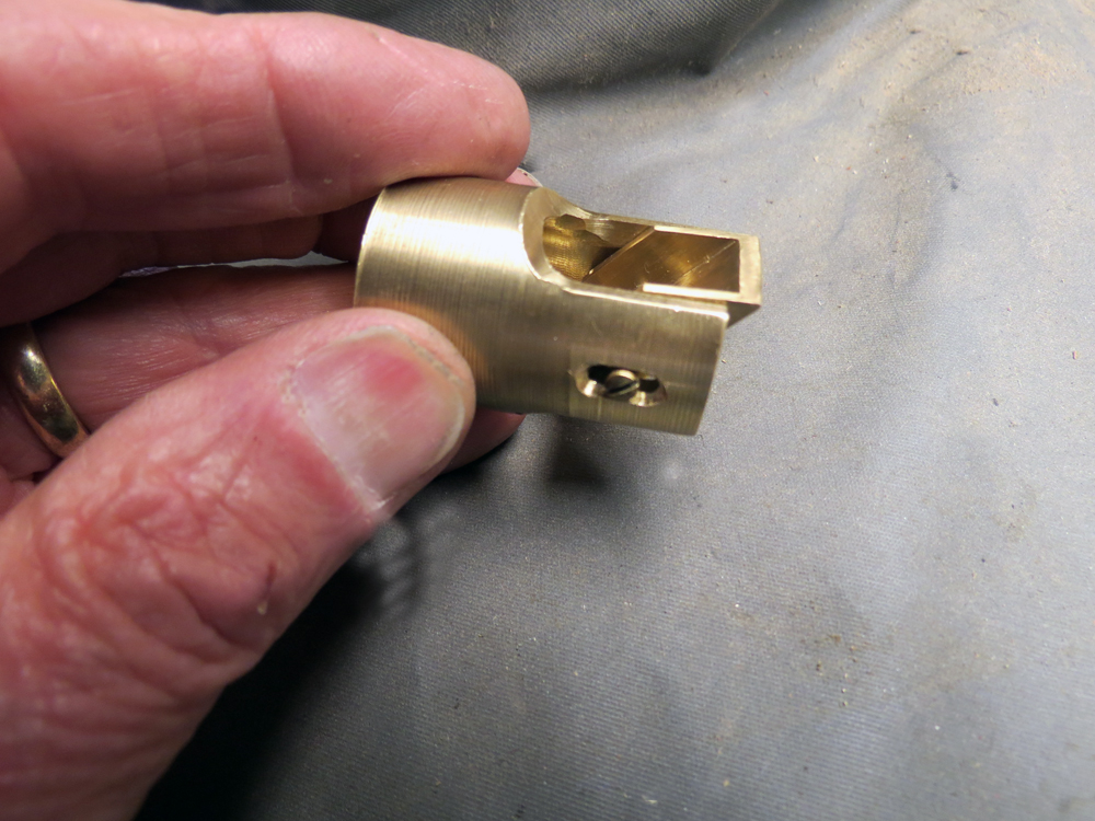
below cutting the "V" slot in the knife edge mirror fixture.

Above, The knife edge holder roughed out. The inside detail for holding the primary lens is finished
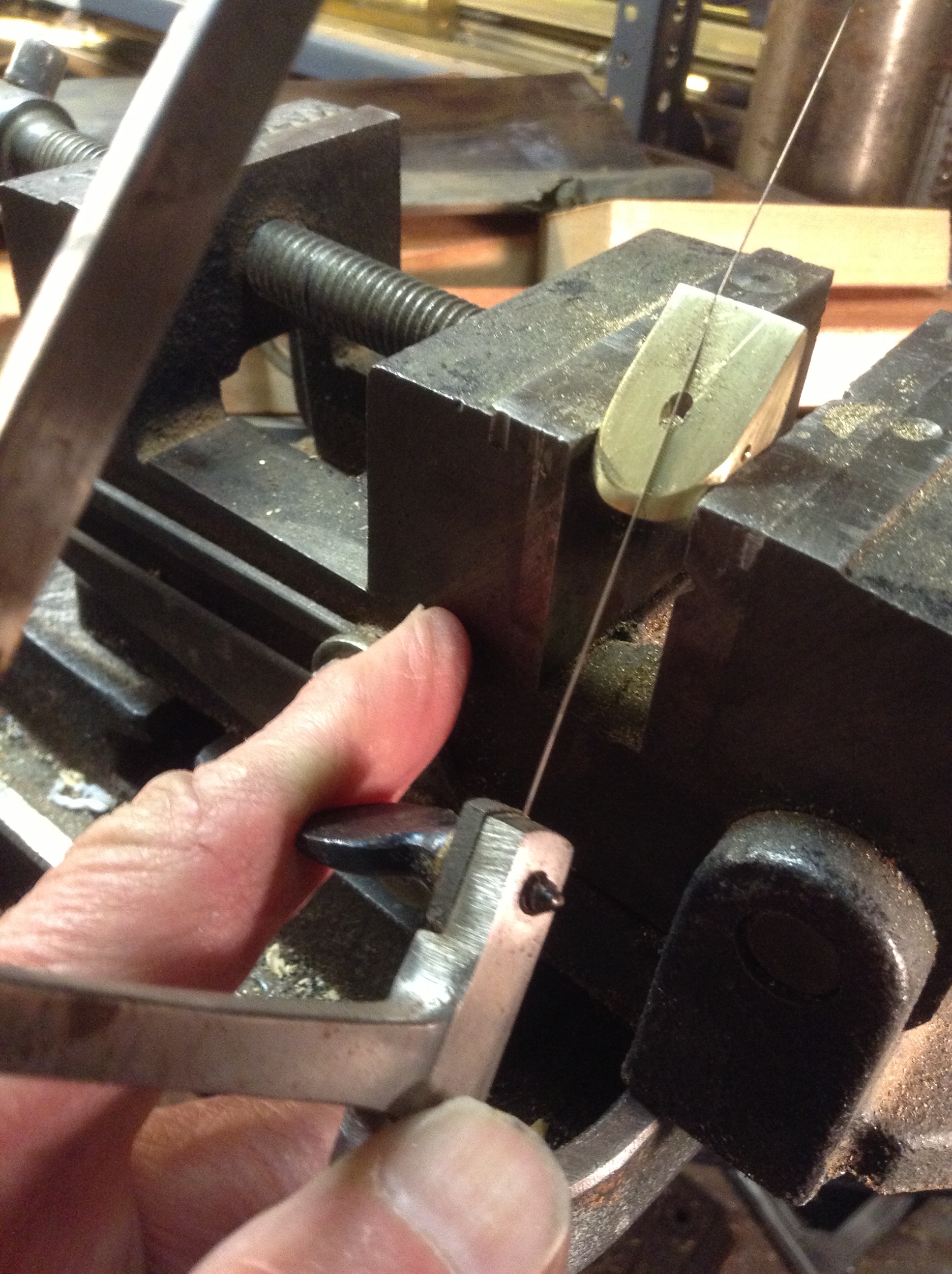
Above, Cutting out the v slot for the mirror knife edge fixture.

Above is the the Varley eyepiece holder being turned in our lathe to its conical shape.
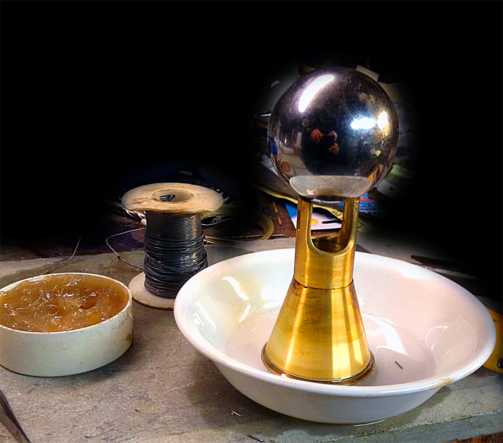
Above, the heavy ball is holding the parts together for silver soldering of the eyepiece.
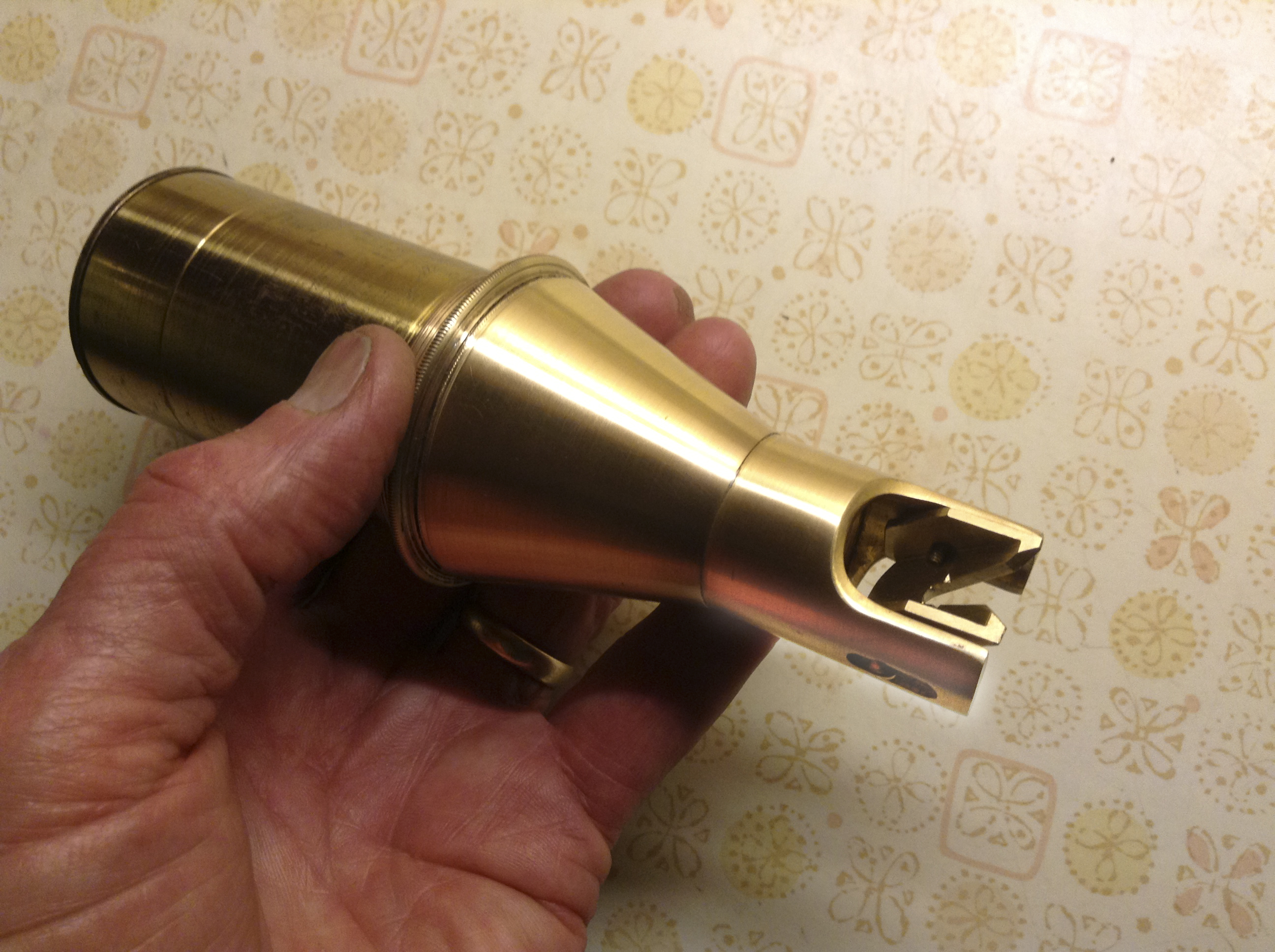
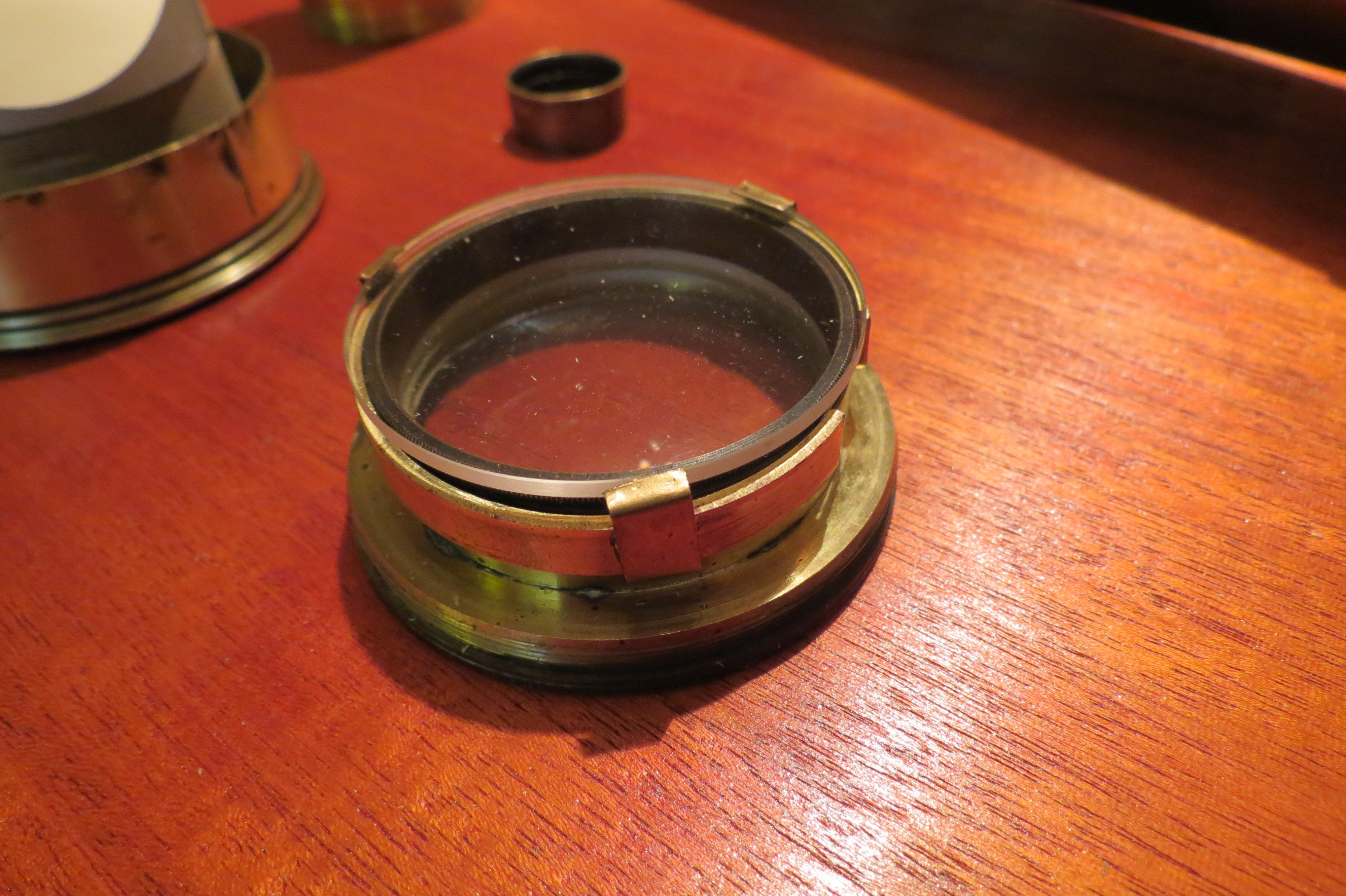
The finished Varley lens components minus the mirror assembled and prepared for finishing.
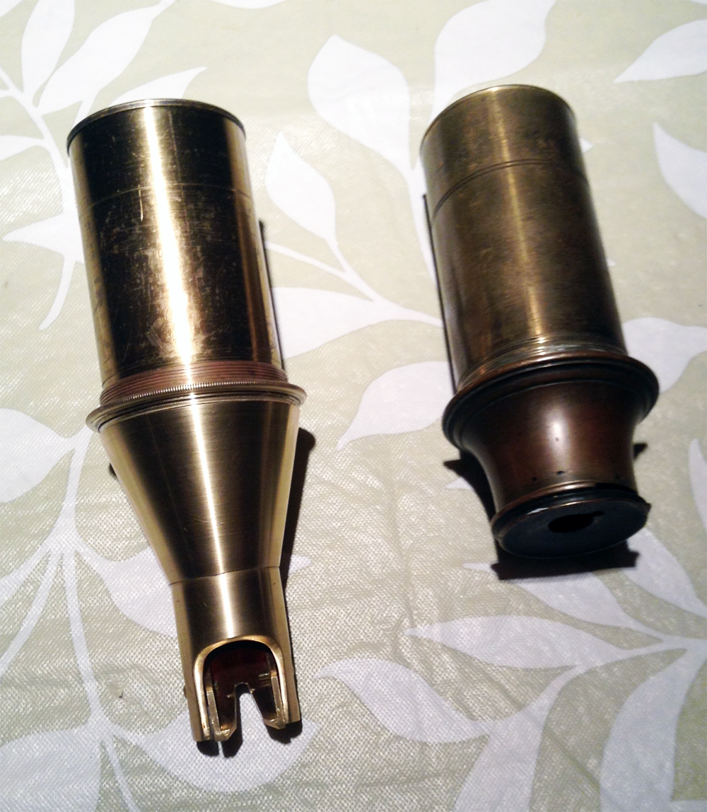
Above is a comparison of the Varley and traditional lens that
came with the telescope.
Either could be used preserving the original telescope.
An important requirement in handle important instruments of the period.
 l l |
 |
 |
| Prototyping the telescope stand. Jim and our "bestest" oldest daughter designing and making the telescope table and stand. | Checking the critical eyepiece with its knife edge to be installed . | Checking and designing the eye relief. system. It needed extra distance built into lenses, compensating for extra distance taken up from the right angle view. |
 |
 |
 |
|
The top most lens fixed on the original objective was our removable field distance shortening lens to let the telescope operate in the short distance available in the museum.*** This lens was an exact copy of Galileo's working telescope which we replicated for the Galileo Museum in Florence Italy. |
An optically flat right angle mirror for adjusting height angle of view. It is out of glass not speculum metal which probably used by Varley. | The sun shield and mechanism for holder the rotating optically flat mirror. |
We have hundreds of photos and video recordings of
the construction, testing, and designing of this remarkable instrument.
The results were beautiful and technically very good because of the
initial design by Spencer Browning .
Varley